The
Lafforgue's Field Propulsion Thruster
LFPT
v1.0
Built and tested by
Jean-Louis Naudin
created on January
20, 2002 - JLN Labs - Last
update January 30, 2002
All
informations in this page are published free and are intended for
private/educational purposes and not for commercial applications
This is a new test about the Field Propulsion Thruster ( LFPT v1.0 ) patented by Lafforgue ( patent FR 2651388 ).
Tested apparatus description :
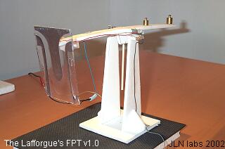
I have used the same setup successfully tested on January 20, 2002, the design has been significantly improved so as to reduce near to zero the leakage current in permanent regime ( when the DC High Voltage is constant ). The thin copper wire previously used to connect the outer armatures has been replaced with a full insulated wire. I have also used a lower voltage ( 9.5 KV DC max ) for avoiding leakage by Coronna effect.

The
Lafforgue's Field Propulsion Thruster v1.0 specifications
|
TESTS RESULTS ( 01-27-02 ) :
When +9.5 KV DC is sent to the LFPT, the leakage current is near to zero ( not measurable in a micro-ampere range ) . The measured capacitance of the LFPT is 4 pF.
In this test, the High Voltage DC power supply is automaticaly switched on/off through the TTL input of the HVPS connected to a function generator.

The pulse period has been tuned so as to
get the maximum amplitude of the beam balance ( T=3.85 sec,
F=0.26 Hz ).
The duty cycle is adjusted to the minimum level ( DTC = 5% ). The
high voltage and the current output are measured through the
monitoring outputs of the HV power supply with a digital
oscilloscope, see the voltage/current curves below :


The resulting upward thrust is weark and can be easily
computed with the LFPT
Calculator

The LFPT motion follows the voltage curve and does'nt consume current. This experiment confirms that there is always a thrust upward in spite of the absence of any leakage current by Coronna discharge in the air.
The purpose of this second experiment is to compare the voltage/current curves of the LFPT with the voltage/currents curves of the electrostatic pressure setup with the areometer already done on January 23, 2002.

I have used the same power supply configuration than the experiment #1 above, the LFPT have been replaced by the Electrostatic Pressure experiment setup with the aerometer.
TESTS RESULTS ( 01-27-02 ) :
The pulse period has been tuned so as to
get the maximum amplitude of the beam balance ( T=1.54 sec,
F=0.65 Hz ).
The duty cycle is adjusted to the minimum level ( DTC = 10% ).
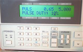
The high voltage and the current output are measured through the monitoring outputs of the HV power supply with a digital oscilloscope, see the voltage/current curves below :


The Aerometer ( Hydrometer ) motion due to the electrostatic pressure follows the voltage curve and does'nt consume current. The similarity of the LFPT and the Electrostatic Pressure experiment seems to confirm that the origin of the phenomenon is similar.
Some documents references :
 FR Patent N°2651388 "Isolated systems self-propelled by
electrostatic forces"
by Lafforgue Jean-Claude - March 1, 1991
FR Patent N°2651388 "Isolated systems self-propelled by
electrostatic forces"
by Lafforgue Jean-Claude - March 1, 1991See also :
 The Lafforgue's
Electrostatic Pressure experiment
The Lafforgue's
Electrostatic Pressure experiment
 The
Lafforgue's F.P.Thruster Solver v2.0
The
Lafforgue's F.P.Thruster Solver v2.0
![]() Email : JNaudin509@aol.com
Email : JNaudin509@aol.com
Return to the LFPT home page