Evidence of an
asymmetric force between the two armatures by Jean-Louis
Naudin Cliquez
ici pour la version Française created on
February 21, 2003 - JLN Labs -
Last update February 21, 2003 Toutes les informations et schémas sont publiés
gratuitement ( freeware ) et sont destinés à un usage personnel
et non commercial All informations and
diagrams are published freely (freeware) and are intended for a private use and a non commercial
use.
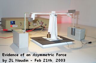
The purpose of this test is to check if the attraction
of the plate ( the aluminum armature ) towards the wire is
stronger than the attraction of the wire towards the plate. So, I
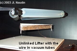
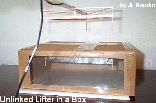
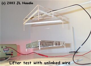
have built two identical asymmetrical capacitors, see the photo
below. These two asymmetrical capacitors are composed of two
armatures, the first armature is the wire and the second armature
is the aluminum plate. The two capacitors have been placed on a
beam balance. The first capacitor, on the left side of the beam
balance, has its plate mobile and its wire fixed and the second
capacitor, on the right side of the beam balance, has its wire
mobile and its plate fixed. The beam deflexion has been limited
so as to avoid a short circuit between the wires and the plates.
The wires have been connected to the (+) of HV power supply and
the plates to the 0 V.
In the photo above : On the left
side of the beam balance, the wire is fixed and the plate is
mobile.
In the photo above : On the right
side of the beam balance, the wire is mobile and the plate is
fixed.
Asymmetrical
capacitor specifications
Aluminum
plate : 75 x 20 mm ( 0.5 mm
thick)
Wire :
copper 1/10 mm diameter
Working
voltage : 25 KV DC
TEST #1
:The gaps between the wire and the plate of the
two capacitors are initially equal.
In the
initial conditions the beam balance is equilibrated and the two
gaps ( wire-plate ) are equal.
When the HV power
supply is switched on, the moving plate is attracted towards the
wire ( see the photo below ).
The test
#1 shows that :
The
attraction force of the plate towards the wire is stronger
than the attraction force of the wire towards the plate.
TEST #2
:The moving wire is closer to the plate than
the other side.
In the
initial condition, the moving wire, on the right side of the beam
balance, is closer to the plate than the other side. A small
additional weight has been placed on the left side of the beam
balance. The purpose of this test is to increase the attraction
force of the wire towards the plate on the right side and to
decrease the attraction force of the plate towards the wire on
the left side.
When the HV power
supply is switched on, the moving plate placed on the left side
of the beam balance is still attracted towards the wire ( see the
photo below ).
The test
#2 shows again that :
The
attraction force of the plate towards the wire is still
stronger than the attraction force of the
wire towards the plate.