
The Lifters successful replications
Experimenters Log Book
created on October 10th, 2001- JLN Labs
All informations in this page are published free and are intended for private/educational purposes and not for commercial applications

The Lifters successful
replications
Experimenters
Log Book
created
on October 10th, 2001- JLN Labs
All informations in this page are published free and
are intended for private/educational purposes and not for
commercial applications
Lifter replications Log Book : Previous Page - Next Page
|
| Envoyé via Internet |
For your consideration for your excellent list
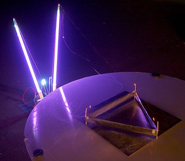
Lifter Mk 3 has custom argon tubes for the upright high voltage wire supports. In addition it has small neon indicator globes at the corners of the lifter itself. Very impressive at night. Not really a high flier however due to the reduced voltage available after the argon's plus the added weight of the small neon tubes. One further feature is the 'crash-land' button. This uses a motorized switch to short circuit the power supply. This causes a loud and bright spark visible low down between the upright neon's in the left picture, the tall argon's flash and the lifter loses power and falls. Power is DC stabilised 30kV 50uA with or without dropping resistor of 300K. Control for "take-off" is with a switch mode controller.
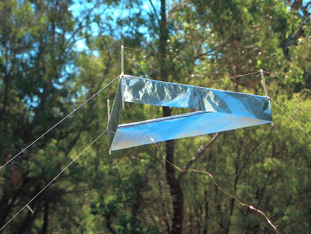
Lifter Mk 2 is an older lighter version shown some feet in the air and in a bush setting.
The power supply is sold as a 30 kV 50 uA stabilised supply which runs off 24 V.
However,
my measurements are:
Input...............................................................24
V 0.80 A = 19 W
Output (measured after argons).
no load (argons only but no wires to lifter) ?.... 30 kV
100 uA
plus HV Meter (100 uA FSD movement) ....28 kV 130
uA = 3.6 W
plus lifter (no dropping
resistor) .....22 kV 400 uA
= 8.8 W
ie Net current is around 270 uA and net power used by lifter is
around 5 W.
The
argon tubes drop about 500 V each with the load of the lifter. so
I lose about 1 kV in operation (but gain 50 KV of coolness)
The plain vanilla lifter (ie no attached neons) used for these
masurement is 30 cm a side triangle and jumps up very smartly to
its tether limit at 2 feet.
With
thanks
Peter (Tesla Downunder)
http://tesladownunder.iinet.net.au
|
| Envoyé via Internet |
Jean-Louis,
I am excited to say that I have successfully lifted off. It
took me a few tries to get the wire's height just right,
but perseverence paid off. I would be honored if you would add
me to the Successful Lifters Log.
I have included a picture.
Regards,
-Jim
|
| Envoyé via Internet |
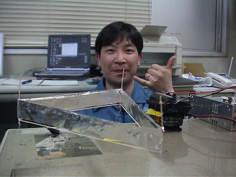
Nice to meet you Mr.JNaudin.
I am Japanese (MITAKA-City TOKYO). YAG-LASER Welder Engineer.
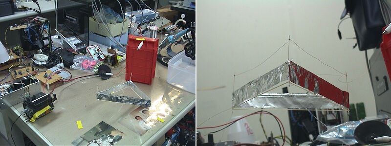
I'm glad to complete a LIFTER. 4times I mistook. But I 'd to try and try.
And I am going to try to make some LIFTERS.
That's all. Have a good LIFTERS.
DoKA
|
| Envoyé via Internet |
Bonjour Mr Naudin.
Je vous ai déja contacté il y a quelque temps,
et voici la suite de mes travaux sur le lifter.
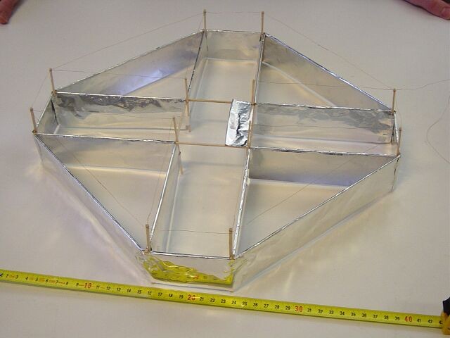
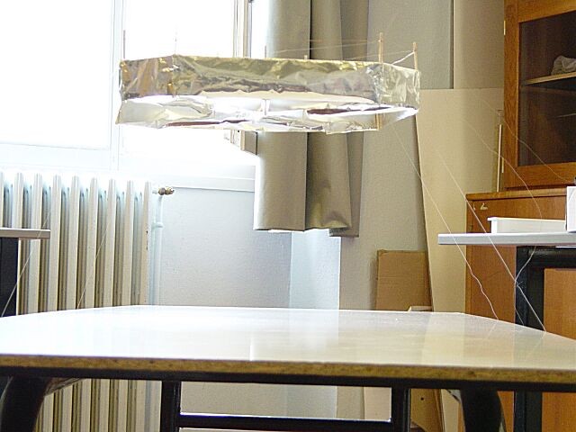
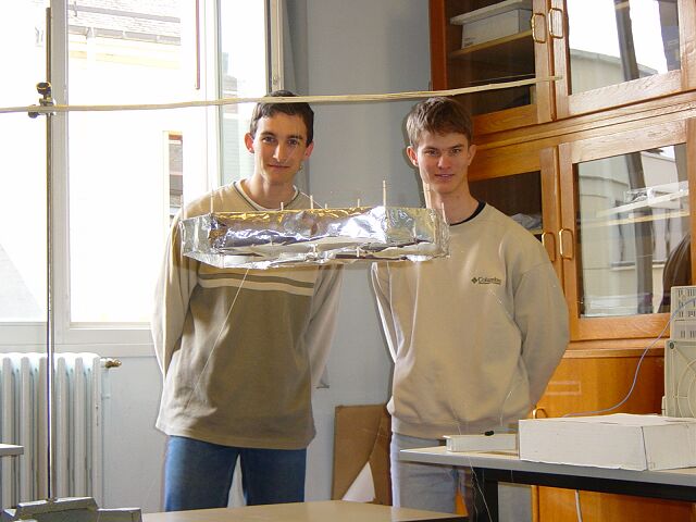
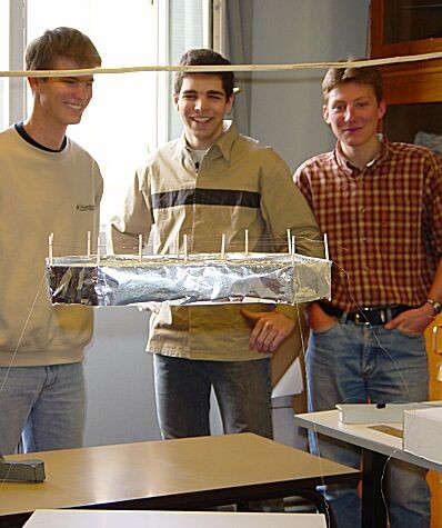
Le spécimen dont voici des photos dispose d'une capacité de
déplacement horizontal via la cellule centrale...
Pour alimenter ce lifter, nous utilisons deux écrans d'ordi, un seul n'étant pas en mesure de délivrer assez de courant. La cellule centrale, qui n'est pas encore tout à fait opérationnelle, est alimentée par un troisième fil qui arrive par le haut, que l'on relie via un interrupteur artisanal à l'une des deux alims dès que l'engin est stabilisé en l'air. Nous devrions en savoir plus sur son fonctionnement d'ici quelques jours.
Merci de votre intérêt et bonne continuation,
Benoît Vuillermet, au nom de mon équipe.
Benoît Vuillermet/Florian Delmas/Sylvain Morel/Sébastien
Roux-Rosier ( France ).
|
| Envoyé via Internet |
Dear Jean Louis,
A few months ago I was alerted to your
web site by a friend of mine, i was instantly impressed, and I
felt overwhelmed to make some sort of contribution to this
exciting field..
So, after looking at, and taking note of the specfications of
your Lifter 1, I set about designing and constructing my own
Lifter.
I alwasy think big, (I always have :) hehe..) and as yourself and
many other people have sucessfully constructed and flown your
Lifter 1, I took that as enough of an example to create my own
design
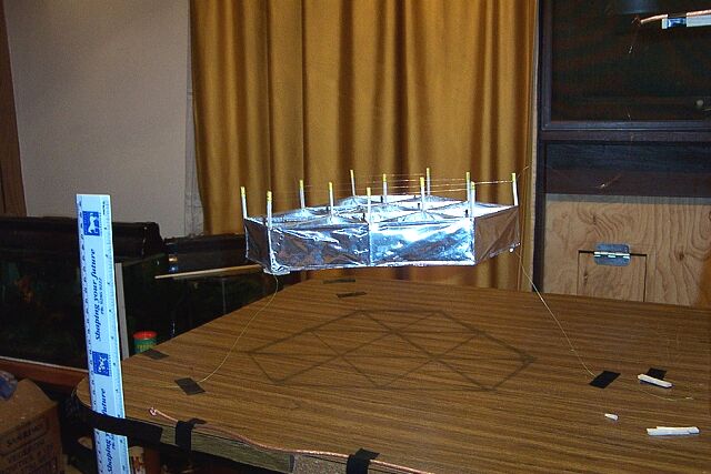
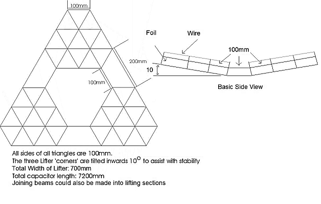
It is basicly an equilateral triangle. In each corner are the
lifting stages. Each stage consists of a 400mm equilateral
triangle, but with the top 100mm removed to create a distorted
hexagon shape (see enclosed diagram), within each 'hexagon' are
more triangles, for a total capacitor length of 2400mm!
Allowing for a 100mm gap between the 'hexagons' this gives a
three way length of 700mm, and a total capacitor length of
7200mm!
As you can see from the picture, the corners are tilted inwards
at a 10 degree angle to each other. As the thrust is directed
through the device, I figured that this tilt would help to
stabilize the craft when it was in flight.
Construction began in early February, however, I became a little
impatient, (I wanted to see it fly!!) so once I had finished one
of the 'hexagons', I set about finding 30Kv from an old 14"
monitor I had lying around..
At appoximately 3:45am on Saturday 20 March (after a few attempts
and some adjustments to both the wire height and the tether
length) it achieved lift.. :)
I noticed that the longer it was opperating the more stable its
lift was and more the wire glowed. Another very interesting
point to note is the corona discharge between the wire and the
top edge of the foil.. It is easily visable with the light off as
a bright purple light, and, is even just visable with lights on..
unfortunately, my camera is unable to pick it up, (video or
still).
Sitting there with the lights off watching the glowing wire is
all well and good, but the smell of the Ozone coming from the
lifter can't be good, still stong smell even with the windows
open :)
Well, now that I have been up all night working on this... I
guess it's time I go to sleep.. I shall post the completed Lifter
as soon as possible.
Merci beaucoup Jean Louis :)
Gene Lomas, Melbourne Australia
|
| Envoyé via Internet |
Hello Mr. Naudin
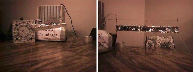
I have successfully completed a basic Triangle Lifter. After
coming across your site I decided to try building a lifter for
myself. So, today I got a monitor from my cousin and started
building. After about 2 hours I had the monitor ready, and my
lifter ready to go.
On my first attempt it jumped a bit but ultimately failed. I
found it was too heavy. I then cut the bottom triangle out of my
lifter to reduce the weight, and it worked great as it took off.
It was really stable too.
My Lifter measured 30 CM (12 inches) on each side.
The power source is a 26kv monitor
Thanks for all the helpful advice on your site. I am going to try
a new design in a couple of days.
I have attached some pictures of the maiden flight.
Shaun
Victoria, B.C
Canada
|
| Envoyé via Internet |
Dear Mr. Naudin!
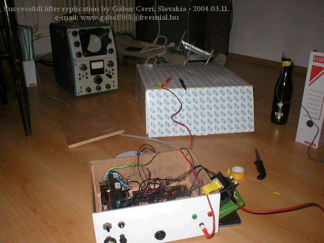
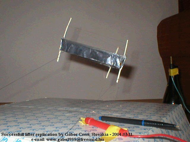
Here are the photos and datas from my lifter:
- it works from cca. 20 to 30 KV with a current of about 1-3 mA
- it works on max frequency, which can be produced by the 555 IC
- it`s weight is about 3-4 g
I have included the photos from the lifter 1.0, and from my
Hendershot coils with full documentation.
I`m very happy, because this is only my second device /the first
was the BingoFuel Reactor/, and it`s works very well too.
Yours Truly
Gabor Cseri
|
| Envoyé via Internet |
Hi
have made a sucesful lifter as seen i small video enclosed it is
basic design 210mm each side and 30mm gap using balsa wood/cotton
buds and wire from an electric clock power supply was a 14 inch
colour tv also i have found that cd roms make very good
conducters and am working on using them at momment i believe a
really true anti gravity machine with no power sauce other than
magnets and mercury based upon the earths core and its magnetic
field and the way it generates it will let you know more when i
have better results
thanks
dave wilks
england east sussex
|
| Envoyé via Internet |
Hi,
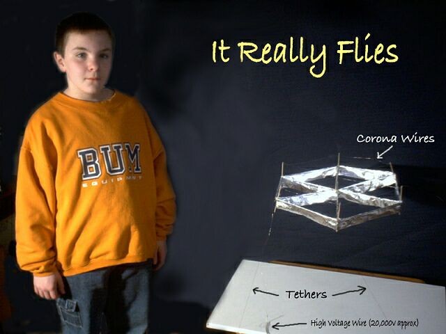
My name is Brodie and I am 11 years old and I live near
Vancouver, Canada.
After looking at your site I decided to build a lifter for my
science fair project. I named by craft the “Vril” – this is
because in World War II many people thought that the Germans had
UFO like crafts that might have worked on the same principle as
the lifter.
My first prototype was not that efficient because it had a lot of
arcing, however my second one worked like a charm. I am also
planning on building a larger lifter to carry a payload of an
ant.
I thought it was a good the way you proved the lifter does not
use ionic winds. Here is a picture of my lifter.
Thanks for the ideas and good work
Brodie
|
| Envoyé via Internet |
Thank you!
I have since successfully replicated the ‘hexalifter’.
I also replaced the 30g magnet wire with 50g stainless steel
wire. I did observe the improved lift, loss of visible corona,
and quieter operation that was mentioned on using the smaller
corona wire.
Soon I will begin to experiment with my own ideas and will share the results if anything surprising or unexpected is observed.
…Joey
Joseph R. Furr
MCP, MCT, MCSE, CCA
President
Reliant Systems, LLC

|
| Envoyé via Internet |
Cher Mr Naudin,
Après quelques hésitations et doutes sur le principe du Lifter
je me suis lancé dans sa réplication très bien expliquée sur
votre site.
Eh oui, plus aucun doute, ça marche! On a beau
connaitre des équipements de haute technologie, avec une manip
comme celle là on a tout de suite l'impression de participer à
une découverte. Quelle joie de voir son propre lifter voler dans
la cuisine!
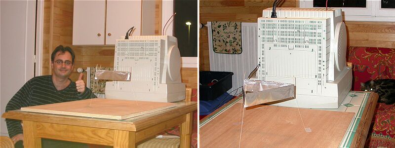
J'ai utilisé une alim HT de 27.5kV d'un vieux moniteur couleur
et une résistance série de 330kohm.
Le lifter décolle très vite et reste très
stable. Ci-joint quelques photo et une petite vidéo.
Merci et bonne continuation
Gabriel Gaubert
|
|||||||||
| Envoyé via Internet | |||||||||
Hallo,
I am living in Czech Republic and I have success with flying
lifter. Sorry my english is very bad.
Ing. Robert Lanicek
city Brno
Czech republic
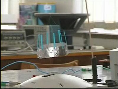
I can send video.mpg flying lifter (VCD format mpg1)
typical experiment (high voltage from monitor)
|
|||||||||
| Envoyé via Internet | |||||||||
Dear JLN,
After trying to get a working powersuply built for two years I
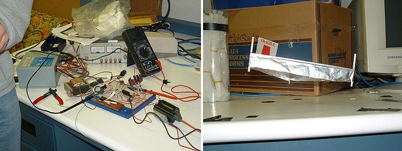
was finaly able to replicate the lifter v1.0. Atached are some
pictures of the lifter in action and my slopy powersuply setup.
The lifter is poorly constructed but some of the information I
used was bess guess from the instructions found on your site. I
found your instructions on makeing a lifter v2.0 to be mutch
better. I am planing to have the lifter v2.0 built and working in
2 or 3 weeks.
Thanks for the loads of information on your site, even if some of
the math is a bit beyond my understanding.
Kevin Schneider
Houghton, MI
USA
--
Kevin Schneider
a.k.a. Ifandbut
1st year EET student
"No Ifs, Ands, or Buts about it."
|
|||||||||
| Envoyé via Internet | |||||||||
I have successfully replicated the lifter 1.0 tonight!
30g enamel magnet wire (noisy!).
200mm single triangle configuration.
I think I am underpowered a bit, and had to modify the length of
my +/- leads to keep it from sagging towards the leads. Also, I
started with a 10” tether height, which I eventually reduced to
about 8” for more stability. I’m looking forward to
experimenting with different configurations, & I’ll keep
you updated on the status of any interesting
observations/improvements.
I took a corona exposure looking for consistency and hotspots,
which I attached as well.
Thanks for the jump start!
Joseph R. Furr
Little Rock, Arkansas

|
|||||||||
| Envoyé via Internet | |||||||||
Bonjour M. Naudin
Je suis fier de vous faire part de mon succes après trois jours
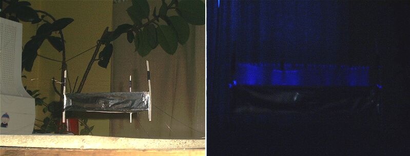
d'efforts j'ai obtenu un vol stable avec un lifter de 20 cm de
cotés
je joint deux photos dont une montre le bleu qui se dégage
L'optimal est-il d'avoir un maximum ou un minimum de ce bleu?
Merci d'avoir semé cette connaissance sur la planète
J'ai beaucoup d'idées pour faire des essais
Je vous en ferai part si je découvre quelque chose de nouveau
Lifter replications Log Book : Previous Page - Next Page
Return to the Lifters Builders page