
The Lifters successful replications
Experimenters Log Book
created on October 10th, 2001- JLN Labs
All informations in this page are published free and are intended for private/educational purposes and not for commercial applications

The Lifters successful
replications
Experimenters
Log Book
created
on October 10th, 2001- JLN Labs
All informations in this page are published free and
are intended for private/educational purposes and not for
commercial applications
Lifter replications Log Book : Previous Page - Next Page
|
|||||||||
| Envoyé via Internet | |||||||||
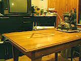
Hi to all!
Well, I made some tubular lifters,
one of them flew in quick time mov, see attach.
Regards!!
Name: Kresimir
Age: 15
Country: Croatia, Europe
|
|||||||||
| Envoyé via Internet | |||||||||
Bonjour Mr Naudin
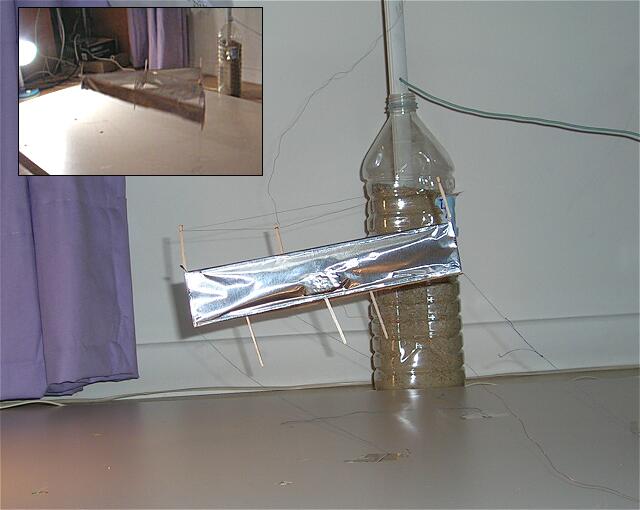
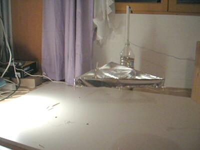
Je me permet de vous prendre un peu de votre temps dans le but de vous montrer mes experiences de Lifter chez moi.
j'ai réalisé un lifter v1 qui vole tres bien et un lifter v2 qui s'envole avec tellement de force que les scotch qui retiennent le lifter ont ete arrachés ! hélas il ne reste pas droit et part violemment vers le coté opposé au fil positif.
voici donc deux videos tres courtes (format quicktime) et une photo que j'espere voir sur votre site. Si il est possible de mettre une photo de mon lifter v2 sur votre site aussi je vous l'enverrai.
Voila je voulais vous remercier de m'avoir donne cette passion des lifters et j'y consacre beaucoup de temps.
au revoir
Michael
|
|||||||||
| Envoyé via Internet | |||||||||
Hello!
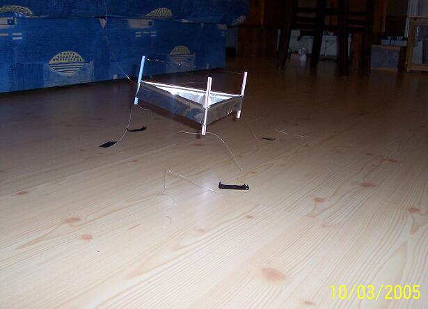
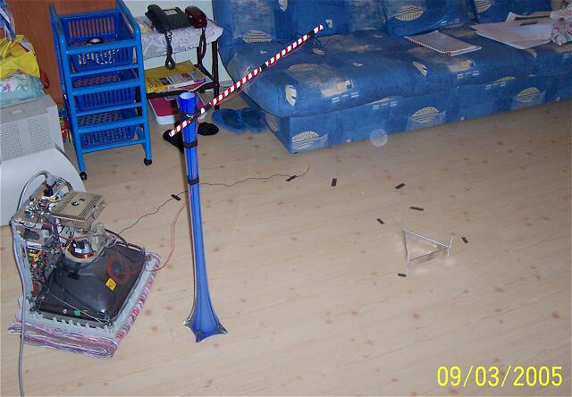
I am Paul from Timisoara, Romania.
The Biefeld-Brown effect is really amazing.
I made yesterday this lifter in only 1/2 hour, from juice tubes,
aluminum foil and copper wires. It is 20 centimeters wide.
The power supply is from an old monitor.
A+ !
Paul.
|
|||||||||
| Envoyé via Internet | |||||||||
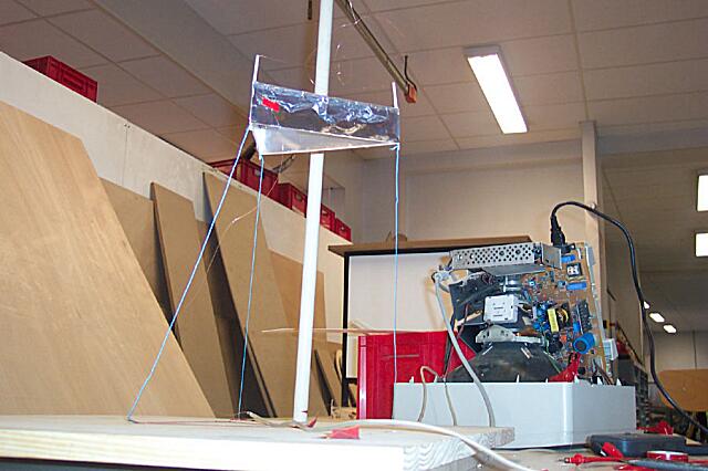
Bonjour j’ai fait ce lifter avec un ami dans le
cadre d’une uv de réalisation à l’utt (université de
technologie de Troyes)
Merci pour tout et merci pour ce site très intéressant !
Vous trouverez vidéos et photos ici : http://fotosupone.free.fr/photos/lifter/
Cordialement,
Vincent Amador
|
|||||||||
| Envoyé via Internet | |||||||||
Bonjour cher monsieur Naudin, nous sommes
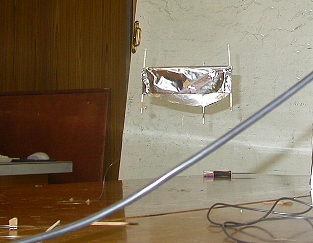
étudiants à Paris (Mérouane et Romain) et on a reproduit un
lifter, le modèle de base tout simple uniquement pour l’instant.
L’originalité vient du fait qu’on a utilisé des pailles
pour le construire, c’est plus léger que le balsa et le
montage est bien plus simple puisqu’il suffit de les emboîter.
On a utilisé du bois pour les pieds et pour fixer le fil.
Il nous a bien fallu 6 ou 7 prototypes ratés avant d’aboutir
et de trouver le coup des pailles.
Ceci étant dit je tiens à vous féliciter pour votre site et
pour tout le travail d’expérimentations que vous avez
entrepris avec succès.
En attendant de vos nouvelles, je vous remercie et vous salue.
Mérouane.
|
|||||||||
| Envoyé via Internet | |||||||||
Mr. Naudin
First I would like to compliment you for a wonderful
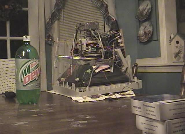
website. I was able to recreate the lifter experiment only
needing the resources contained within your site.
I did not realize how difficult it would be getting a
lifter to fly successfully. I went through a few lifter design
changes, but eventually got a modified version of your Lifter1 to
function. Mine is a bit smaller in dimensions, and the corona
wire sits much higher due to my power source. (My power source
was a 17" computer monitor.)
I also trimmed the collector and bottom basla wood
supports for less weight. Finally though, I acheived stable
flight.
Here is a link to the video of the lifter in action.
(Would attach but cannot due to size limits.) Also here is a
link to a .jpg screen capture from the video.
Video: http://www.neuralimpulse.com/Lifter-OKonski.avi
Picture: http://www.neuralimpulse.com/mikeslifter.jpg
Please let me know if you have trouble downloading these
files. The .avi is a Divx file and requires the latest version
of Divx, may not work with anything before v5.2
This fight was completed by myself, Mike O'Konski, as
well as the assistance of my sister, Laura O'Konski who helped
with the project. Looks like we may be #283. :)
Looking forward to more successful replications, and new
flights with new desgins.
Thanks again!
Mike O'Konski
PS. I have documented my first flight on a web page. http://www.neuralimpulse.com/lifter.html
|
|||||||||
| Envoyé via Internet | |||||||||
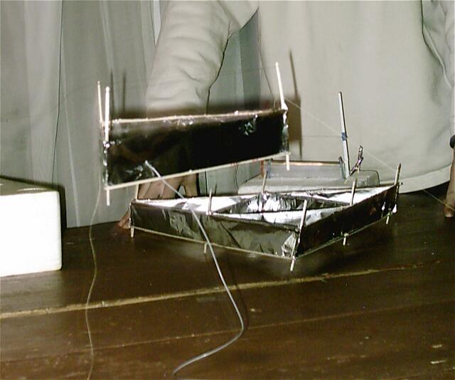
J'ai réussi à faire voler un lifter. Comme promis je vous envoie une photo. Malheureusement, mon appareil numérique n'étant pas de très bonne qualité et l'eclairage étant imparfait, ces photos ne sont pas extremement explicites. Lors d'une autre tentative, j'essaierai d'en faire des plus réussies
Je vous remercie pour toute l'aide que vous m'avez apporté pour effectuer cette experience.
Au revoir
Pierre-Louis Toussaint
Courbevoie (banlieue parisienne)
|
|||||||||
| Envoyé via Internet | |||||||||
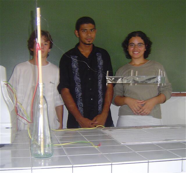
Merci pour votre aide qui a été de la construction du lifter par votre précieux site à vos informations que vous nous avez envoyez par mail sur certaines questions qu'on se posait.
Notre tpe est maintenant presque fini et tout est au point. Nous avons étonné les professeurs qui pour la plupart ne connaissaient pas, juste quelques-uns qui avaient vu une fois à la télé réunionaise. Les professeurs de physique ont même été passionnés par notre projet et voulaienttous le voir voler! Je vous remercie encore une fois
Laurence, Thomas et Ridwan de l'Ile de la Réunion
|
|||||||||
| Envoyé via Internet | |||||||||
Dear Mr. Naudin!
I think this Lifter Project fantastic. This is one of my first
lifters, similar to Lifter1.0 but it's lighter. The first
succesfull flight was on 2005.01.30.
I used 25kV.
Gergely Klujber

|
|||||||||
| Envoyé via Internet | |||||||||
Cher Monsieur Naudin,
Après 1 an, 2 mois, 2 semaines, 1 jour, 1 heure, 15 minutes et
27 seconde, soit exactement 38279727 secondes depuis la première
fois où j'ai commencé à envisager la construction d'un
prototype à Antigravité, de type Lifter, un nombre colossal
d'heures de travail, pratique et théorique, d'essais
infructueux, mon prototype vole !
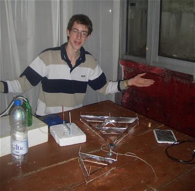
Je vous envoie donc les photos comme Pierre-Louis vous l'avait
promis. Cela fait en effet quelques semaines que nous travaillons
ensemble sur ce Projet, et voir enfin ce modèle voler fut pour
nous une véritable consécration ! Pour l'alimentation, nous
avons construit une alimentation THT branchée sur le secteur
réalisée par Flavien, le troisième homme de notre petit
groupe, qui s'est averrée fonctionner à merveille pour cet
usage.
Nous avons également testé un Générateur de Plasma Froid, comme vous pourrez le voir sur la photo ci-jointe... Nous comptons en effet maintenant nous atteler à la construction d'un autre prototype d'engin volant utilisant un Plasma Froid, je vous donnerai plus d'informations dès qu'il fonctionnera !
Encore Merci pour votre site toujours aussi passionant et qui nous a permis de réaliser un vieux rêve !
Cordialement,
Philippe Castera
|
|||||||||
| Envoyé via Internet | |||||||||
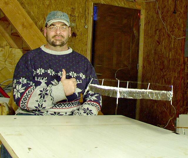
I made it in one hour. I did not make anything with a
measureing tool so I don't know the dimensions. I just did what
'felt' right =)
I used:
tiny straws
aluminum foil
hot glue gun with standard hot glue
some steel or silver wire from stripping stranded wire of its
insulation (I just know it isn't copper).
Power supply is a old monitor I found that had been discarded.
Flys tons better than previous ones I measured very carefully
with.
--
Sojourner
|
|||||||||
| Envoyé via Internet | |||||||||
Hello Jean-Louis,
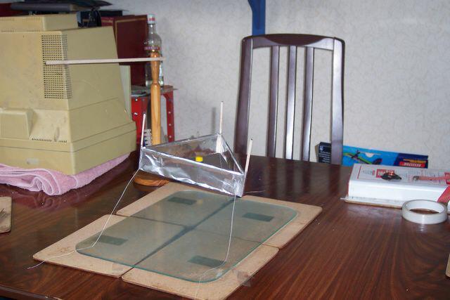
I am pleased to report that I have made my first successful
flight of a lifter today.
I used an old monitor as the power supply and followed the
instructions provided by Timothy Ventura for the lifter.
Please find links to my photographs and video at:
www.renrut.demon.co.uk
'Keep up' the good work!
Mark Turner
|
|||||||||
| Envoyé via Internet | |||||||||
bonjour jean;
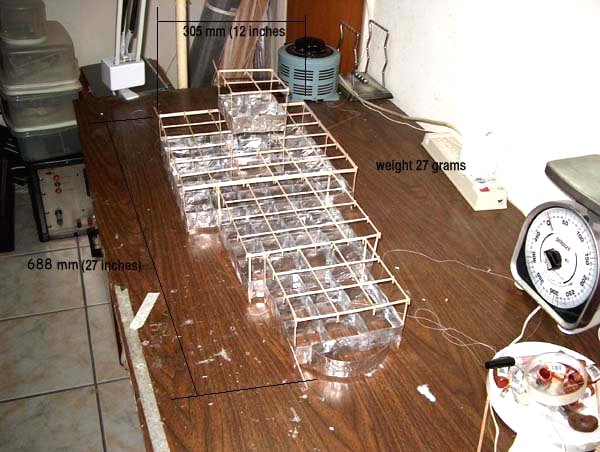
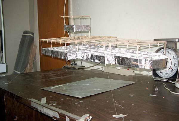
chris gupta from south florida
This was very time consuming work, many cells very difficult
job.
i left this on my work table and one day my lamp loosened fell on
it and crushed it.
|
|||||||||
| Envoyé via Internet | |||||||||
bonjour jean
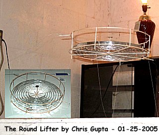
chris gupta from south florida
to build the round lifters properly some important equiptment is
necessary.
a steam machine,a hot air gun and a large diameter gasket cutting
tool, and i also use aluminum tape with conductive adhesive.
my emitter is aluminum wire 32gage.i have made from 6" dia
to 30"dia.
For
more pictures and construction details, click here
|
| Envoyé via Internet |
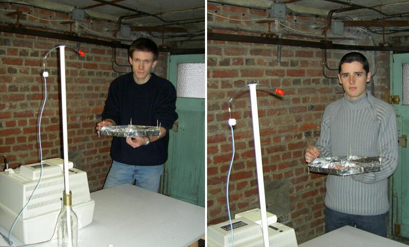
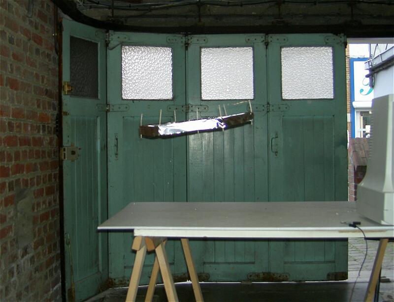
Voila donc notre deuxième hexalifter qui décolle avec une alimentation de 26kV . Nous avons pour cela, comme vous nous l'aviez conseillé, refait le lifter avec moins de plis sur l'armature en aluminium pour obtenir plus de stabilité que notre première version. Le résultat est tout à fait satisfaisant. Nous avons donc réussi deux hexalifters consécutifs, ce que nous devons à vos explications irréprochables. Nous vous remercions donc, moi et mon collègue de votre aide pour la réalisation de notre lifter.
Hexalifter de 40 cm de large
Alimentation: 26kV (écran couleur)
Vanderstiggel Florian et Guiselin Julien
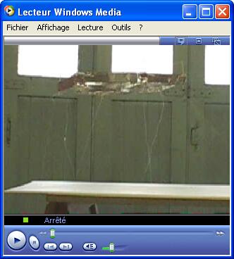
Cliquez sur l'image pour voir la
vidéo (703 Ko )
|
| Envoyé via Internet |
One of our first lifters we built. First
successful flight Sunday January 9th 2005 in Utah USA.
Shane Beeder
Vernon McPherron
We've included a small video, as you can see it doesn't fly very
stable. If you or anyone knows how to make it fly a bit more
stable, please respond.
Vernon McPherron (vernon@xnote.com
)
Shane Beeder (shane@xnote.com)
|
| Envoyé via Internet |
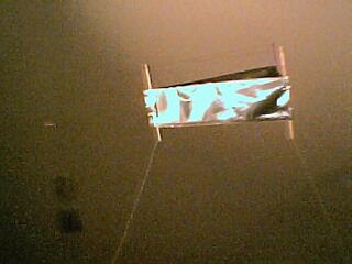
Bonjour nous revoilà gael et seb,
comme vous nous l'aviez demandé voici quelques photos de notre
lifter...
merci d'avoir répondu à notre dernier mail et merci encore pour
toutes vos explications.
Nous vous enverrons les résultats de notre tpe ,
En attendant merci et bonne route...
Cordialement , gael et seb ...
|
| Envoyé via Internet |
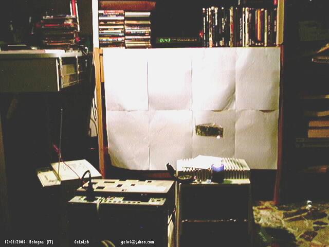
I have just to say that this is a very lightweighlifter.Made only of metal and plastic, without bars at the sides of triangle.The monitor give me a 24kv dc and the ion wind is able to extinguish a little flame.
My high regard to Townsend Brown.
Gemma Lorenzo
Bologna Italy 12-03-2004
|
| Envoyé via Internet |
I have
finally completed and installed my lifter in the Gravity
Discovery Centre in Australia.
Some considerations for this public display were:
HV protection is provided by an acrylic surround (the most
expensive part at over AUD$1000).
Interactivity provided by firstly a "Soft landing"
rotary control to control the pulse width modulated 24V to the HV
supply. Secondly with a "Crash landing" button (red, of
course) in which there is a loud spark as the 30kV supply is
short-circuited and the lifter drops 18 inches suddenly. The
supply doesn't like being shorted so there is a 17K dropping
resistor and a 570pF 40kV doorknob that provides the energy for
the spark. Kids love this button.
Colour is provided by the argon tubes which are the HV
supports and alter brightness as the current draw changes. There
are three spot lights of red, green and purple to give
reflections of the foil of the lifter. These were made from
arrays of 8 x 5000 MCD LEDs each.
Educational information is provided by an accompanying poster
or by the tour guides.
Reliability. Light toy kite string was used instead of
thread at a small weight penalty. A lot of care was taken with
the hot gluing (and 2 spare lifters were made). The impact point
at the feet was also reinforced with hot glue. On earlier lifters
I needed to put some tape on the HV feed wires to prevent them
getting agitated. On this one, I left the enamel coating on the
feed wires and the problem was much better so hopefully wire
fatigue will be delayed.
RF interference is a potential problem. Particularly since
there is a multidetector cosmic ray recorder on the other side of
the rear brick wall. Leaving the enamel on the feed wires seems
to have reduced the RF and I also have about 10 turns of
inductance on the feedwires wound around the argon tubes.
Ozone will be produced and there is a 6 inch gap between the
roof of the enclosure and the wall where this will escape. The
mildly darkened theater that it is in is large with perhaps a 40
ft ceiling and is air conditioned.
Mains safety. I have an external switchbox which has a fuse
and a microwave oven mains RF filter.
I know of only one other lifter on public display in a
"Robot museum" if I recall. I would be interested
to know of any others.
Peter (Tesla Downunder)
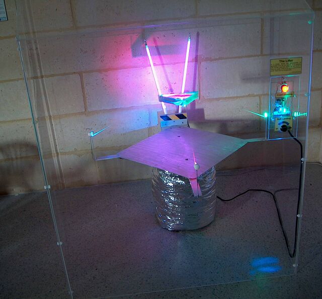
More details on my site http://tesladownunder.iinet.net.au/Lifters.htm
|
| Envoyé via Internet |
Hi Jean-Louis,
Quite some time ago I emailed you about my first successful
lifter here in New Zealand. Although I have not done much work
with lifters since then, I have come up with what I think is a
new way of building lifters. I do not know if anyone has done
this before, but here is what I have done:
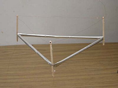
I created lifters with much less balsa wood than previous lifters
by using the aluminium foil as the horizontal beams. Instead of
covering a balsa frame with aluminium, I rolled up the aluminium
into a tube about 6mm diameter. Once rolled up the aluminium
becomes quite strong so it can be used as structural component. I
used sticky tape to hold the foil as a tube by running the tape
along the length of the tube after the tube was rolled.
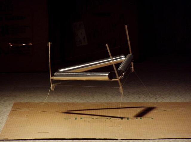
The lifter in the picture was constructed from a 30cm by 5cm
section of foil which was rolled up to a 6mm tube. The tube was
then folded twice to form a triangle and balsa uprights were
added to each corner to support the copper wire. The resulting
lifter is an equilateral triangle with side length 10cm. An old
computer monitor was used to power the lifter.
I am not sure how much lift was generated compared to other
lifter designs, but I do think there is potential in eliminating
most of the balsa wood from the lifter design since the balsa
does not generate any lift. I would like to share this idea so
that someone who has more time may be able to experiment with
this concept.
Thanks,
Andrew Murphy
|
| Envoyé via Internet |
Bonjour Jean Louis,
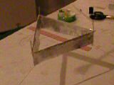
My name is David Snyder and I live in Vanceboro North Carolina
USA. After many attempts I have built my first functional lifter
and I am looking forward to many more. The power supply is a
GRAHV35 from amazing1.com. I do not know the weight of the lifter
(have not found a scale yet) but I have calculated it to be about
10 grams, less the positive and negative leads. Attached is a
MOV. More pics and info later.
v/r
Dave Snyder
|
| Envoyé via Internet |
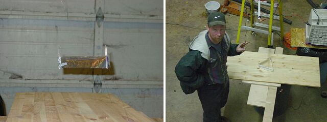
I have worked on a few diff. lifters and here are some pics, they are actually about a year old, but better late than never right?
I also have a hypothesis that states that the faster the lifter moves the more efficient it will become. If you have a lifter that is having a hard time achieving lift put a fan over it blowing directly on it and it will now fly becoming more efficient. Wich would also summarize that once the lifter is in movement, the faster it goes the less power coefficient it will take to propell it! Or i also feel that by keeping power relative you could eventually reach light speed, given that the structure could withstand the forces at hand!
I would also like any info possible on building a higher (200kv-300kv) variable output supply.
THANKS & GOOD LUCK TOO ALL
J.KARGER
|
| Envoyé via Internet |
Dear mr Naudin,
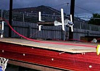
My name is Scott, I am an engineering Patternmaker from Melbourne Australia. Here is a picture of the tubular lifter my son and I have built. It is powered by an old monitor.
We would like to thank you for the information on your site, and wish you the best for all your work.
|
| Envoyé via Internet |
Dear Jean-Louis Naudin,
Thanks for the great docs on your web site!
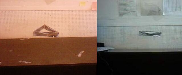
We have succeeded making the lifter work.
At first there was a small problem - probably the lifter was too
heavy. We cut about 1cm from the bottom of the whole construction
and it started flying.
The power supply is from 14 inch display, the lifter is built
according to the instructions on your site ("How to build
your own lifter"), but the bottom 1cm has been cut.
We also noticed some (strange?) behaviour: we sticked extra balsa
wood sticks as weights on the sides of the lifter. The strange
thing was that the lifter seemed to actually lift itself more
from the side with the extra balsa wood stick (although that side
was heavier than the other sides).
We're not sure if this is some kind of debalancing, and also not
sure that our observations are correct: more observations are
needed in order to clarify.
We also noticed that if you loose the top wires they are starting
to vibrate.
Your work is really great!
Best Regards,
Nikola Mihaylov, Tihomir Tihomirov - Bulgaria
|
| Envoyé via Internet |
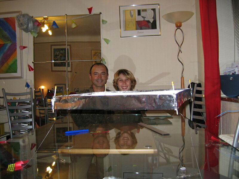
Merci M Naudin
Grâce à vous j ai pu avec mon fils réussir à fabriquer et
faire voler mon 2eme lifter
Ce moment inoubliable n’est ^pas près de quitter notre
mémoire !!!
Notre 1er essaie a été un échec mais le résultat du second
était infiniment plus satisfaisant
Et nous ne comptons pas nous arrêter là !
Merci encore
Claude et Thibaud .
|
| Envoyé via Internet |
Dear Mr. Naudin,
I have successfully reproduced your hexa lifter in Czech Republic at nuclear power plant Dukovany. I take high voltage from old 15¨ monitor.
Best Regards
Michael Krocil
Dukovany Czech Republic
Lifter replications Log Book : Previous Page - Next Page
Return to the Lifters Builders page