How to build a
Lifter v2.0 demonstrator by Jean-Louis
Naudin Cliquez
ici pour la version Française Created November
25, 2002 - JLN Labs - last
update April 28, 2003 Toutes les informations et schémas sont publiés
gratuitement ( freeware ) et sont destinés à un usage personnel
et non commercial All informations and
diagrams are published freely (freeware) and are intended for a private use and a non commercial
use.
This tutorial
explains you how to build yourself a 40cm wide Lifter v2.0 for
your demonstrations and your experiments.
Required
material :
- A light weight
balsa wood board ( 15/10 mm thick ). You will find balsa wood
board in any RC Hobby shops,
- a kitchen aluminum sheet ( 12 µm thick ),
- a thin copper wire ( 1/10 mm diameter ) extracted from a simple
multiple wires power grid cord,
- a tube of cyanoacrylate universal glue,
- a hobby knife ( a cutter with a sharp and brand new blade ),
- a stripper ( Conrad Ref: 0229 458-30 ),
- a 50 cm ruler,
- a wooden plate ( 50x50 cm at least ) as your working surface,
- scotch tape,
- a paper pen.
Construction
time : about 1 hour
Cost :
about 1 Euro...
STEP 1
:
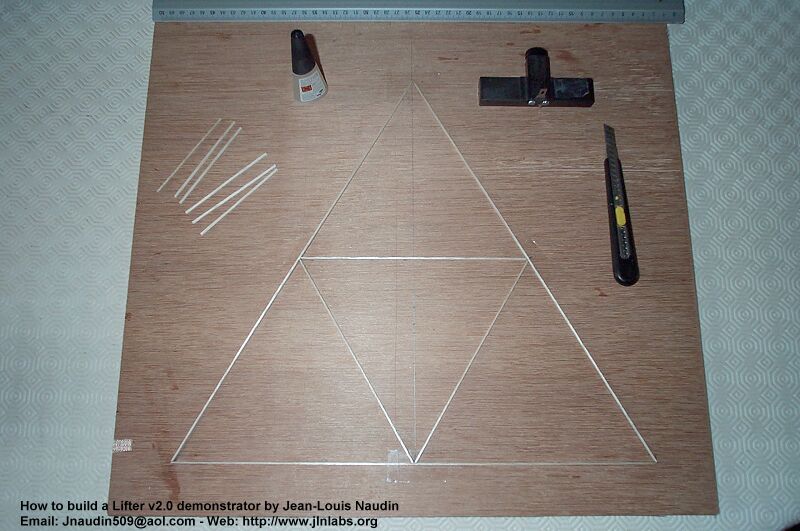
1-A) Preparing
the working surface : On the wooden plate,
draw a 40 cm side equilateral triangle with a smaller 20 cm side
equilateral triangle embedded in the middle as shown in the photo
below. Protect each triangle intersection by putting an adhesive
tape on your working surface, this will avoid that the
cyanoacrylate glue the balsa wood of your Lifter on the wooden
plate ( the working area ).
Don't
forget to build light, a Lifter v2.0 weight is less than 7g
1-B)
Cutting the balsa sticks : Cut with the
stripper or with the cutter, the 2 mm wide balsa stricks :
- 6 sticks
( 90 mm lentgh and 2 mm wide ),
- 6 sticks ( 400 mm lentgh and 2 mm wide ),
- 6 sticks ( 200 mm lentgh and 2 mm wide ).
1-C) Put
the three 400 mm sticks and the three 400 mm sticks on the
drawing of the wood plate as shown in the photo below. Be
carefull, the stricks are placed on there smallest
edge. Glue
there intersection with cyanoacrylate. Wait 1 minute, then with the
blade of the cutter unstick very carefully the triangular frame
from the working area .
1-D) Put
away the triangular frame. Handle with care, this is a very fragile
structure...
Then, build a second triangular fram as explained in 1-C), and
put away your new triangular frame so has to clean up your
working area .
STEP 2
:
2-A) Draw
on your working area rectangular 400x40 mm in the horizontal
direction with three 90 mm vertical lines showing the vertical
sticks of your Lifter ( see the drawing below ). This shows the
front view of your Lifter in red. Protect each intersections by putting an
adhesive tape on your working surface.
2-B) Place
carefully and maintain vertically the two triangular frames (Handle with care, these ares a
very fragile structures ) as shown in the photo below, then glue all the
90 mm sticks on each intersections.
2-C) The main frame
of your Lifter v2.0 is finished, now, you may place it
horizontally on your working area.
STEP 3
:
3-A) Cut (
with the cutter and the ruler ) 6 rectangles in a kitcheen
aluminum sheet ( 12µm thick ) at the dimensions indicated below
:
- 3
rectangles 405x45 mm,
- 3 rectangles 205x45 mm,
3-B) Glue
the aluminum sheets with the cyanoacrylate glue as shown in the
photo below :
CAUTION
: The aluminum
sheet must exceed about 5 mm the upper edge of rectangular frame.
3-C) Pull
down and stick the upper edge of the aluminum plate on the balsa
wood stick. This creates the leading edge of your Lifter.
The aluminum sheet must
cover the upper stick of the balsa bood frame
3-D) Apply
the same construction method for the others aluminum sheets.
3-E) The
aluminum plate of your Lifter is now finished, you need only to
mount the thin copper wire on the vertical sticks. The wires are
fixed on the vertical sticks with cyanoacrylate glue.
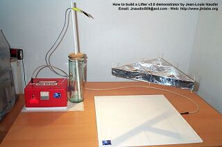
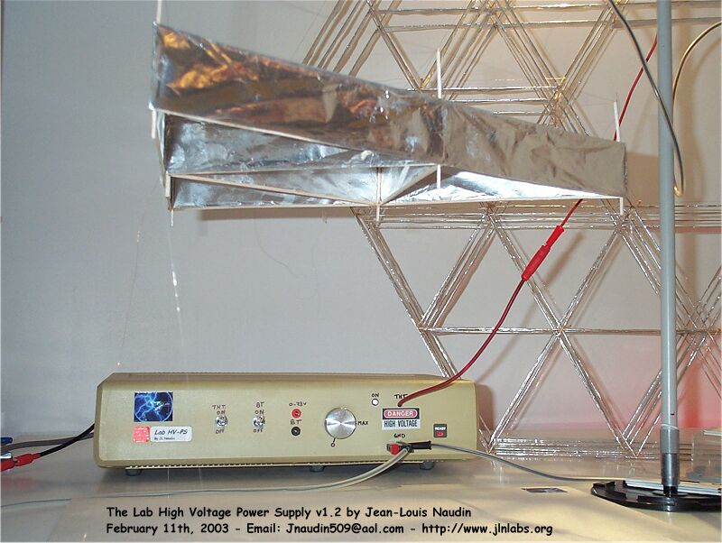
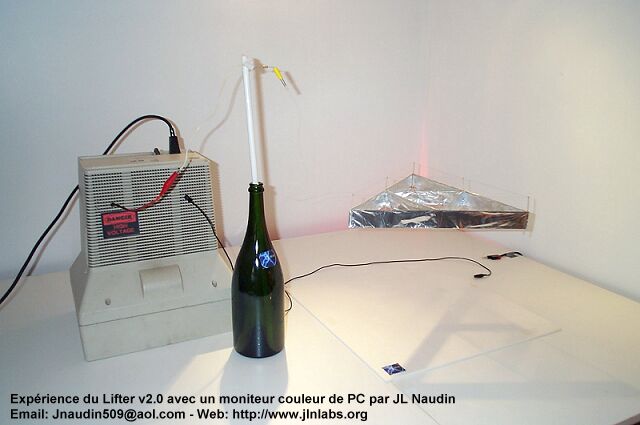
The Lifter v2.0 is
finished, the +30kV is connected to the wires through a thin
copper wire ( 1/10 mm ) on its left side as show on the photo
above. On the opposite side, the aluminum plate is connected to
the 0V ( or the ground ) with a small aluminum tape. Your HV
power supply must be able to deliver about 500 µA at about 30KV.
I recommend you to protect your power supply with a 470 kOhms
(2W) resistor in serie with the HV output. The
Lifter1 is maintained on the surface base with 3 thin nylon
threads to avoid that it escapes to the ceiling...
Notes
: If you want to get a lighter Lifter, you may remove the bottom
triangular frame, this will improve the upward thrust and it
flight enveloppe.
BE CAREFUL, USE
EXTREME CAUTION !!!, this
device uses High Voltage, ALWAYS
switch off the input and discharge the output to the ground through 10k/2W
resistor before
touching it. These plans are not intended for the
inexperienced. User of this document should be very
carefull and experienced in High-Voltage electronics to
try anything out ! If you do it the risk of any results
is just yours. I take no responsibility of anything that
might happen.